FITTING
INSTRUCTIONS
Arcadian AP150/200/250 Horizontally Tracked Door Gear
For use on one-piece metal, timber or GRP garage doors
MAXIMUM DOOR WEIGHT: AP150 = 68KG
(200lbs) AP200 = 90kg (200lbs) AP250 = 114kg (250lbs)
Minimum timber frame size 70 x 70mm
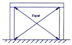
Frame must be square - check diagonals
Frame must also be square with brick opening
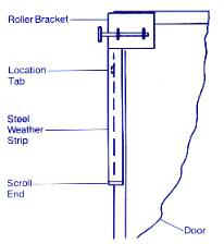
Fit the top roller brackets to the door as shown using No.12 x19mm self tapping screws.
TAKE CARE NOT TO DRILL THROUGH THE DOOR FACE
Wedge the door in the opening and allow 10mm side clearance, 10-12mm clearance between the top of the door and the header and at least 8mm ground clearance
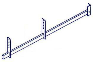
Position the track over the roller and temporarily support the track with rope or a webbing strap allowing up to 40mm fall to the rear and keeping the track square to the door. With the track just touching the bottom of the roller drill two 6mm pilot holes in the middle of the slots. Fix using two M8 x 60mm coachscrews
Cut the track support brackets
to suit, slide them onto the tracks & fasten to suitable supports with
M8 x 40mm coachscrews & M8 washers, for diagonal stabilizer bracing, lengths of punched angle should be cut and attached to the support brackets
using M8 nuts & bolts (the upper end should be secured in
place with M8 x 40mm coachscrews later when the door is open)
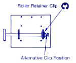
Fit the rubber buffer into the hole at the end of the track
Note: AP200 & 250 gear is supplied with four track supports, two must be fitted to each track as shown
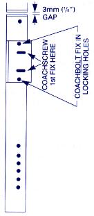
Fit the lower weather strips onto the door posts allowing a 3mm gap below the top side weather strips using No. 12 x 19mm self-tapping screws. Identify the activating arm holes & drill two 5mm pilot holes then secure the arm brackets into position with M10 x 60mm coach screws through the slotted holes, ensure the brackets are parallel to frame then drill 10mm holes through the frame & secure through the post with coach bolts. Door must not be opened until these coach bolts are fitted & tightened
Fit the bottom bracket to timber or G.R.P. doors
using two M8 x 40mm coach screws and the square clamp plates
provided. TAKE CARE NOT TO DRILL THROUGH DOOR FACE
Note: On steel doors
use M8 nuts & bolts, corner bracing plates may be
required in order to provide a place to fix the lower arm brackets -
these are available separately. (see our order form)
Important : The activating arm MUST be square to both door & frame
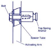
Double check that the buffers are in position on the tracks - Then OPEN the door and prop it in the fully open position taking great care as it will be very heavy. The top spring anchor bolt is supplied fitted as shown in the third hole down from the top. (refer to Step 10 for balance adjustment)
Apply grease to the groove in the spring anchor bolt and attach the spring. Hook the spring adjuster bolt onto the bottom spring loop. Fix the spring anchor bracket to the door post using two M8 x 60mm coach screws in the position that allows the spring adjuster bolt to go just through the bracket. (pilot hole 5mm) Take up the slack & tighten the springs no more than 25mm at this stage.
Check the spring anchor bolts are fully tightened
Remove the door prop and push the door back to the buffers. If the door touches one buffer first the track alignment will require correction. i.e. If when viewed from behind the door the left wheel is not touching the buffer, move both tracks to the right. When the alignment is correct tighten the track fixing brackets & secure the diagonal track stabiliser brackets with M8 x 40mm coachscrews.
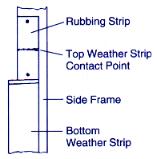
In order to prevent the top weather strips damaging soft timber frames, metal rubbings strips are provided, these should be positioned on the door posts with clout nails as shown in sketch
It is important to lubricate all the moving parts at least once a year
1./ Oil the pivot points on the activating arms
2./ Oil the roller wheel ball races
3./ Grease the spring groove in the spring pivot bolts
4./ Grease the contact points on the frame rubbing strip & door
Open the door about half way so that the activating arms are horizontal and carefully let go. If the door sinks you'll need to apply more tension to the adjusting bolts until the door will balance when half open. If you are unable to get the door to balance you will need to adjust the spring anchor pin position. Prop the door in the fully open position then remove a spring. If the door had a tendency to sink, move the spring anchor pin down one hole. To reduce the spring assistance move it up one hole. Re fit the spring & repeat this procedure on the other side. Remove the prop and re-check the door and adjust the spring tensioning bolts until the door will balance when half open. When a satisfactory balance has been achieved fit the spring adjusting bolt lock nuts & tighten.
One final check. -- The tracks should not be supporting the weight of the door when closed, a simple test for this is to check that you can rotate the rollers easily by hand when the door is closed.
IMPORTANT SAFETY
PRECAUTIONS
ADJUST THE SPRINGS ONLY WHEN THE DOOR IS IN THE OPEN POSITION
Use a prop to secure the door in the open position before removing
springs