FITTING INSTRUCTIONS
Arcadian AP100 Horizontally Tracked Door Gear
For use on one-piece metal, timber or GRP garage
doors weighing up to 45kg max
(100lb)
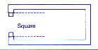
Recommended timber frame size 70 x 70mm
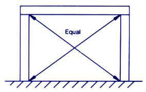
Frame must be square, check diagonals
Frame must also be square with brick opening
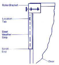
Fit the top roller brackets to the door as shown using No.12 x19mm self tapping screws. If the opening height is less than 2134mm (7'), you may mount the tracks higher by inverting the roller bracket so that the roller is further up on the door.
TAKE CARE NOT TO DRILL
THROUGH THE DOOR FACE
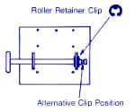
Insert the rollers and secure with
the circlips in the inner grooves on 50mm frames, or the outer grooves on
70mm frames
Wedge the door in the opening and allow 10mm side clearance, 10-12mm clearance between the top of the door and the header and at least 8mm ground clearance
Position the track over the roller and temporarily support the track with rope or a webbing strap allowing up to 40mm fall to the rear and keeping the track square to the door. With the track just touching the bottom of the roller drill two 6mm pilot holes in the middle of the slots. Fix using two M8 x 60mm coachscrews
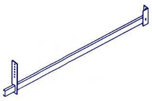
Cut the track support bracket to suit, slide it onto the track and fasten it to a suitable support with an M8 x 40mm coachscrew & M8 washer, for diagonal stabilizer bracing a length of punched angle should be cut and attached to the support bracket using an M8 nut & bolt (the upper end should be secured in place with an M8 x 40mm coachscrew later when the door is open)
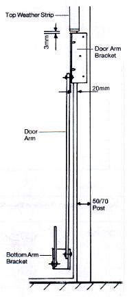
Fit the door arm bracket onto the door post allowing a 3mm gap between the top side weather strip and the arm bracket with the door arm bracket protruding past the door post into the opening by 20mm. Drill a 6mm hole through the top hole and secure the bracket into position with an M8 x 60mm coachscrew, ensure the bracket is parallel to frame then drill and secure the two remaining fixings
Fit the bottom bracket to the door by drilling two 4.5mm holes at the end of each slot and secure with four 6.5mm x 25mm Hex head self tapping screws & washers.
Note: Corner bracing plates may be required in order to provide a place to fix the lower arm brackets to steel doors - see our order form
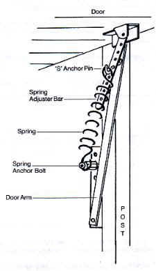
Spring anchor pivot pin position
The main door arm bracket has four punched holes to accept the spring anchor
bolts, for lightweight doors the pin should be inserted in the bottom hole
(hole1) for heavier doors (up to 45kgs or 100lb max) the pins can be moved
to hole 2 or hole 3. Note: the top hole should never be used as this may
result in the springs being over stretched and damaged.
OPEN the door and prop it in the fully open position
Fit the spring anchor bolts on the bottom hole of the door arm brackets
Locate the spring anchor
bracket into
the spring adjustment bar (use an upper hole for heavy doors, a lower
hole for light doors)
Apply grease to the spring pivot bolt and pull the spring down and
locate it onto the pivot bolt, do the same on the other side.
Remove the prop and test the action of the door to check for correct spring adjustment. If the door is heavy in the lower half of its travel raise the pivot bolt up one hole in the door arm bracket and repeat the test.
To complete the balance of the door in the top half of its travel, adjust the 'spring anchor bracket up or down the spring adjustment bar. When correctly adjusted the door should balance and stay put in almost any position.
Finally: check spring pivot bolts are fully tightened
Open the door fully and finalise the track support bracket position and secure the diagonal stabiliser brackets with M8 x 40mm coachscrews. Mark where the roller wheels come back to on the tracks, close the door and drill 10mm holes through the tracks 35mm forward of these marks, brush out any swarf and fit the rubber buffers.
Note: The door must stop on the buffers and not on the spring pivot bolts
Open the door, unroll the rubber strip and position top end beneath the door arm bracket allowing 15mm overlap into the door opening and nail to the door post using six 25mm clout nails. Cut off excess at the bottom and repeat for the other side.
Position the striker plates on the door post with the bottom touching the floor and the side projecting into the door opening by 20mm, secure with four No.12 x 19mm self tapping screws.
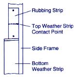
In order to prevent the top weather strips damaging soft timber frames metal rubbings strips are provided, these should be positioned on the door posts with clout nails as shown in sketch
For continued smooth running it is important to lubricate all the moving parts at least once a year
1./ Oil the six pivot points on the activating arms
2./ Oil the roller wheel ball races
3./ Grease the spring groove in the spring pivot bolts
The door should now be operating satisfactorily & the tracks should not be supporting the weight of the door when closed, a simple test for this is to check if you can rotate the rollers easily by hand when the door is closed.
IMPORTANT SAFETY
PRECAUTIONS
ADJUST THE SPRINGS ONLY WHEN THE DOOR IS IN THE OPEN POSITION
Use a prop to secure the door in the open position before removing
springs